Welcome to part 2 of my War Thunder bot series, If you missed it, the intro to the project is in Part 1.
In this part I will go over the techniques used to extract information about the planes current state from the HUD instruments in the "glass cockpit" view. I will be using the OpenCV libraries to do this, specifically OpenCV-Python.
Overview
First, let's take a look at the War Thunder "glass cockpit" as it appears in-game.
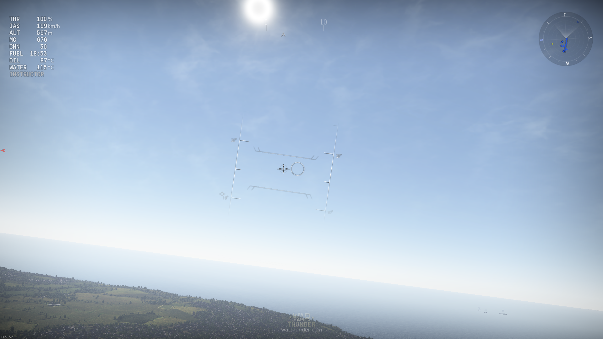
There are three basic sets of instruments here that I want to draw data from, they are:
- The attitude indicator in the middle of the screen.
- The compass at the top-center of the screen.
- The instruments panel in the top-left of the screen.
I want to gather information from all of these. Specifically I need the aircrafts orientation, speed, and altitude. Things like oil temperature aren't useful to the bot's intended purpose (though I will be grabbing them anyways as it isn't much more work).
Preprocessing
Before I can start extracting data the image needs to be processed to make it easier for the computer to read. Right now the HUD elements are white on light blue, hard to see even for a human. Also, the image will look different when the bot is facing a darker or lighter part of the sky, I want to eliminate that variation. Finally, an image reduced to just the two possibilities of black and white is much simpler to analyze.
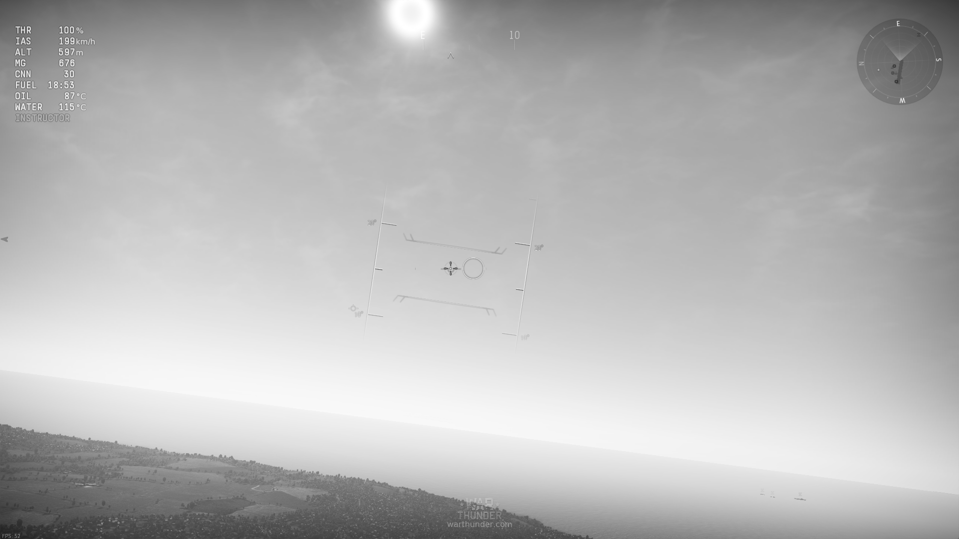
The first step in this process is doing away with color (which provides no information in this context) and turning the image to grayscale, there is nothing fancy about how this works and everyone has seen it many times before.
CLAHE
Next I am going to do a contrast adjustment. To do this I will use the Contrast Limited Adaptive Histogram Equalization algorithm, or CLAHE. The Wikipedia article is a little verbose, but if you ever used the "Auto levels" function in Photoshop it's kind of like that, except it's applied individually to different areas of the image instead of once over the whole image. If you still can't understand that, or have just never used Photoshop before, then perhaps this image of the result will help:
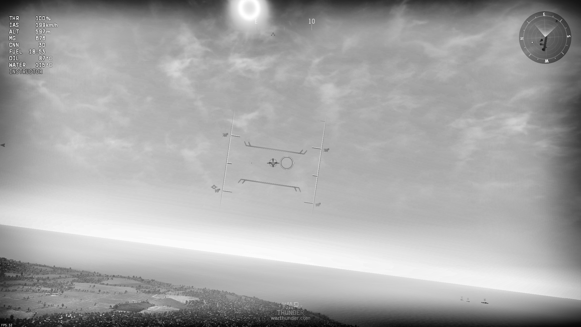
As you can see, this has greatly increased contrast. All the HUD elements are now much clearer, and even the "E" (indicating east) near the top of the image stands out quite well, it was previously nearly invisible against the sun.
Before the next step, I quadruple the size of the image, scaling it to 2x across both dimensions. My trial-and-error testing found that this made the next step work much better.
Thresholding
The next step itself, involves applying an adaptive Gaussian thresholding algorithm (no fancy acronym this time!). This is a little more complex than the CLAHE algorithm, but even if the textual description is confusing the picture should provide a good image of what's going on (pun intended).
The basic idea of thresholding is that you take all pixels in an image brighter than a certain value and make them white, and all pixels darker than that value are made black. Theoretically this should give you a nice cut-out of all the elements you are looking for, because they are much brighter or darker than the background. In practice, however, this only works for the most basic of cases, and even then is often a poor fit.
This is where the "Adaptive Gaussian" part comes into play. Like with the CLAHE algorithm I am going to apply the threshold individually to different areas of the image, selecting an appropriate threshold based on the brightness of the surrounding pixels, thats the "adaptive" part. The Gaussian part means that the surrounding pixels contribution to the threshold is weighted on a bell curve, with the nearer pixels having more weight than ones further away.
If my description was inadiqute, the OpenCV Page on this provides some good examples (look at the soduku puzzle).
The result (with the 2x scaling) is this ugly monstrosity:
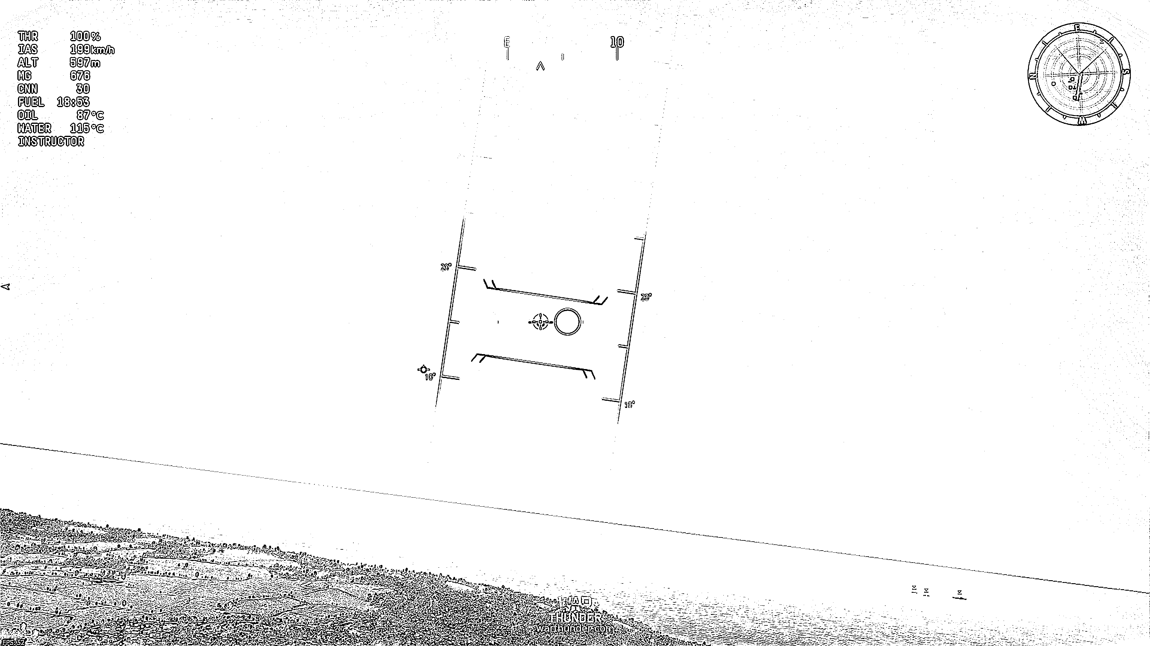
While it may not be nice to look at, it does provide a very consistent and high contrast image, all the things I am looking for stand out and are very distinct. And, it's pure black and white, no greys, all ready for analysis.
Attitude and Heading
With the image now pre-processed, it's time to take some data from it. I should mention here however, that the above steps do not take place over the whole screen as in the screenshots, instead this is only run over the small space surrounding the elements the bot is interested in. This speeds up the analysis significantly.
In-game the attitude indicator and compass actually slide around as you do sharp maneuvers, but this bot should not be doing any fancy-stunt flying so I have provided just a small margin beyond the spaces I am looking in to account for small movements.
Template Matching
The basic idea behind reading attitude and heading relies on looking for the numbers and/or letters that indicate heading and locating them on the screen. To do this I use the template matching functionality of OpenCV. This allows me to give OpenCV an image of what I'm looking for and have it slide the image across the screen, analyzing how much it matches up with what's under it and giving me the results.
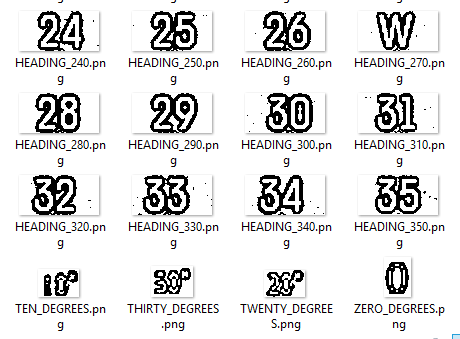
In order to do this, I had to collect images to compare to, and since I am looking at a processed image they would also need to be processed the same way. Since I already had the code to do this, it wasn't difficult to make it just save a small segment of the result as an image (much harder was flying my plane at precisely all the requisite angles and headings to produce source data).
The result was a directory full of images like this:
Once I had these it was just a case of doing a bit of tuning to the minimum confidence cutoff, and a bit of code to eliminate cases where the same spot was detected twice.
Now that I had the co-ordinates of these things, It was time to do something with them.
Getting Heading
I actually wrote the code for the heading detection last, though it is far simpler than attitude detection. Here is how it works:
There's going to be a bit of math here, if that scares you, don't worry! I'm not going to go too deep into details, the specifics are uninteresting anyways. Most of what goes on in this section involves comparing the positions of the detected templates to known locations on the screen.
The algorithm tries to find just one of the templates given to it, and compare it's position to the position at the center of the screen. At this point it knows a heading, and it knows how far away from it it is in terms of screen pixels. With the default settings I determined the ratio between screen pixels and degrees to be about 1/18. By multiplying the pixel offset by this ratio, you get a degrees offset, which is then added to the heading the template represents.
Perhaps a diagram will show it better. (Note, the screenshot shows a full color image, but the actual processing is happening on a pre-processed image)
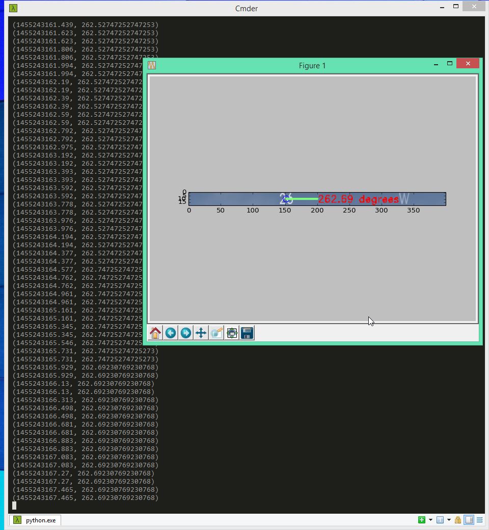
The readout in the background is printing out the timestamp of the capture and the heading captured, separated by a comma. The green line in the diagram represents the offset from the template that was found. The result of 262.69 degrees is found by taking the length of the line, multiplying it by 1/18, and then adding it to 260 (The 26 indicates 260 degrees).
Getting Attitude
If you can understand that, attitude detection is not too much harder. For this I detect two templates and then draw a line between them. Then, from the midpoint of this line I draw upwards or downwards until I am lined up with the center of the screen (Or, more technically, I project the vector between the midpoint of the line and the center of the screen onto the vector normal to the line). Whatever description you followed, I am left with a line that I can use to do the exact same calculation as was done to detect heading.
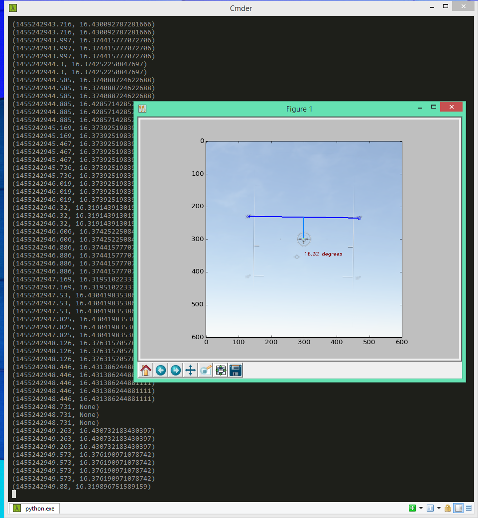
In this diagram the light blue line is the one being measured. The dark blue line is the one drawn between the two detected templates. The output is in the same format, with timestamp and value. In this case taking the length of the light blue line, multiplying by 1/18 and subtracting from 20 degrees gives the result of 16.32 degrees.
The Instrument Panel
That's all and good for the analog instruments on the HUD, but those techniques won't work for the "digital" instruments in the top left, I would need a template for every possible readout!
With that not possible, I turned to Optical Character Recognition, or OCR. OCR takes images of text, and turns them into plain text. The Tesseract OCR library/utility is suitable for my needs and has a python binding (kind of).
Pre-Processing... Again!
But, before I can use OCR on the image there's a bit more pre-processing I need to do to ensure best results. The output from thresholding gives us ugly outlined text, which produces some terrible results when naively run through tesseract.
The processing solution, is fortunately simple, I just do a fill on the image. To hearken back to the Photoshop analogy, it's like the paint bucket tool. The fill is the same color as the outlines so they become hidden and all that's left is the insides of the text. I've also inverted the image to be black text on white, instead of white text on black.
Tesseract
With the processing done I ran Tesseract against my image and observed the output. But even after the post processing, there were some issues...
This is hardly usable. I found it entertaining though that my altitude is 503 watts, and my indicated airspeed has units that are the union of knots and hours, I guess that's still a speed since a union is analogous to a multiplication? (Or maybe disregard that last sentence, it was a bad attempt at a math joke).
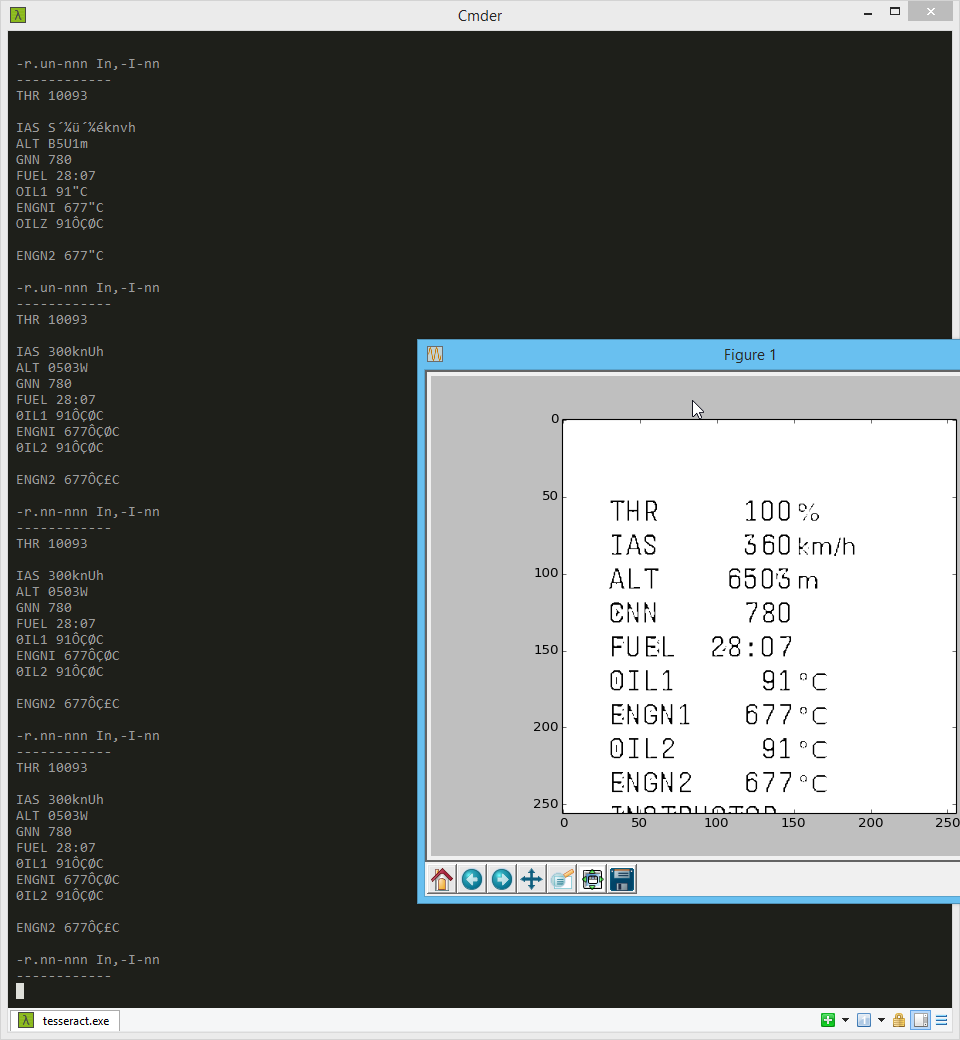
The solution to this, was as unintuitive as it is boring. I just cropped the image area to cut off the units, and voilà:
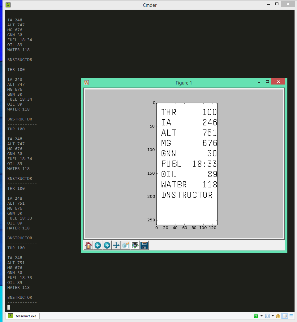
There are still a few issues, notably the "S" in "IAS" has been cut off completely by the second round of pr-processing. Also some recognitions are slightly off: "GNN" "HATER" and "BNSTRUCTOR", but this data is still very much workable.
Next Time
The data recovered from this isn't perfect. The instrument panel has obvious issues with not reading correctly sometimes. And the attitude and heading detection have some error in them, and sometimes they don't read at all (that is, they output "None").
In the next section I will discuss filtering this data to clean up these issues and provide consistent and clean data to the bot.